The ConDiS project is an artistic research project, not a technical research or engineering project. The following chapter focuses therefore on a practical exploration of why the x-OSC was chosen and how the sensor can be used to capture conducting gestures, as is appropriate for my application.
Choice of Sensors
The types of sensors available now is more varied than ever before, and they are becoming more affordable. Given this fast-evolving technology, one must keep in mind that what is news today may be yesterday’s news tomorrow.
To select the type of sensor best suited to the idea behind the Conducting Digital System, the following criteria were proposed:
- Wireless technology;
- High speed and versatile communication —> OSC protocol for accuracy and flexibility;
- Simple and small enough to use but sophisticated enough to fulfill the needs;
- Reliable and not affected by external interference, such as stage lights or human sweat;
- Comfortable/natural for the conductor to wear;
- Low-cost technology.
The following sensors were tested: The Leap Motion Controller, Myo Gesture Control Armband, HotHand, Qualisys Motion Capture Systems, Xbox One Kinect 2.0 Sensor, and x-io Technologies’ x-OSC sensor.
| Brand | Tech. type | Simple/Complex | Reliability | Comfort | Price |
| Leap Motion | USB | _ | _ | + | + |
| Myo Armband | Infrared | + | _ | + | + |
| Hot Hand | USB | _ | + | + | + |
| Qualisys | Infrared | _ | + | _ | _ |
| Kinect 2.0 | Infrared | + | ?
Not enough time to test |
+ | + |
| x-OSC | OSC | + | + | + | + |
Table 1. Evaluation of sensors. + means positive result, – means negative result.
I decided to use the x-OSC for the ConDiS Conducting Digital System for the following reasons:
- Simple to use – The OSC offers various implementations, including real-time sound and media processing environments, web interactivity tools, a large variety of programming languages and hardware devices for sensor measurement.
- Reliability– It uses the Open Sound Control (OSC) protocol for communication between the sensor and the computer. The advantages of using OSC include interoperability, accuracy, and flexibility.
- Comfort– The x-OSC is a relatively small Wi-Fi I/O board that fits comfortably in the hand.
- Price– The x–OSC wireless I/O board is priced within the limits initially set out for creating an inexpensive, fully functional system.
Exploration of the sensor in terms of the project’s practical applications
As stated in the previous chapter, there are numerous existing studies on conductors’ movements. Nevertheless, it was very important for me at the start of this research to better understand in a physical way the response of the x-OSC I/O board to different conducting gestures. The best means of doing this was to physically conduct the electronic sounds myself and explore responses based on various (traditional, non-traditional) conducting gestures. By taking a “snapshot” of these gestures, I could better understand and feel the relevance and robustness of the gestures in conjunction with their conducting function. I was thus in a position to judge their potential for use.
Traditional conducting gestures
The basic traditional conducting gestures are gestures indicating the desired volume, meter, and tempo. With hand gestures, the conductor traditionally indicates an increase or decrease in volume by lifting her arm(s) or making larger (for louder) and smaller (for softer) gestures. The conductor uses different arm gesture patterns to indicate the written time signature—e.g., , —and variable speeds of the arm gestures to indicate the written tempo or metronome. In the next section I describe the test used to find out if it would be possible to use the x-OSC sensor to recognize and learn various traditional conducting gestures.
Up/down motion
Holding a hand open and raising an arm up and down (palm facing the ceiling on the way up and the floor on the way down) produced the following patterns:
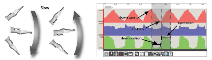
Figure 13. Arm slowly up/down. X-axis peaks at turning points
Raising a hand slowly, as shown in Figure 13 the X-axis (red) indicator showed a gradual move in the direction of the arm, moving up and down. Turning points are also traceable in the form of high and low points. The Y-axis (blue) showed a small but gradual movement in the direction of the arm but apparent peaks at turning points. The Z axis (green) showed an up/down movement when the arm was raised slowly and a down/up motion when lowering the arm. Fast moves up or down were shown at the turning points.
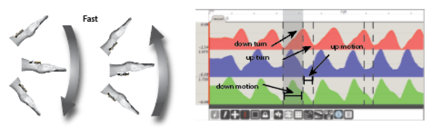
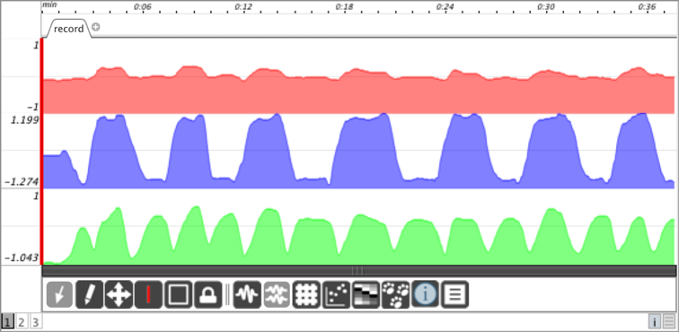
Figure 14. Arm fast up/down. X-axis peaks at turning points
When the arm was raised quickly up and down (Figure 14), a slightly different picture was revealed, especially at the Y- and Z-axes, whereas the X-axis was mostly identical to the case for slow movement. The only notable difference was a minor deviation especially at high points, which was probably caused by computer latency. The Y-axis showed an up/down motion when the arm was raised and a down/up motion when lowering the arm with no peaks at turning points. The Z-axis showed up/down motion on the way up and down/up motion on the way down with no peaks or change of direction at turning points.
Assessment of sensor to capture up/down motion
The accelerometer worked extremely well for measuring the down motion of the hand. The result was very stable with respect to whether the arm was moved, especially the X-axis movement. This provided good enough resolution for use in calculating the arm position in space. Therefore, a decision was made to use the up/down gesture recognition for Volume and Effect control.
4/4 beat conducting gesture – Beat/Tempo
Conducting standard 4/4 beat gestures in two different tempos—fast and slow (metronome 60 for slow and 120 for fast)—resulted in the following patterns:
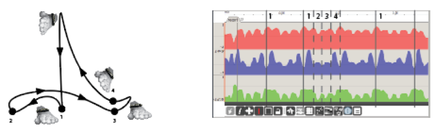
Figure 15. Metronome 60. Counting clear 4/4 pattern
As shown in Figure 15, all the axes X, Y, Z showed traceable patterns when conducting a precise 4/4 beat pattern at a relatively slow tempo, 60 bpm. The X-axis was peaking at every beat (1, 2, 3, 4) while the Y-axis showed reverse motion. The X-axis shows each beat as clear peak points. The Y-axis shows reverse motion with peak points at upbeat to first, second, third, and fourth beat and a definite low point on the first beat. The Z-axis is moderately clear, showing peak points at every beat, although the first and second beats are not especially clear:
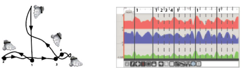
Figure 16. Metronome 60. Counting less clear pattern
When conducting the same tempo with a bit more of a “natural” style (Figure 16), i.e. a very clear downbeat with the remaining second, third, and fourth beats not as strict or more flowing in style than in the first example, the patterns became less clear. The first beat in particular could easily be confused with the fourth beat:
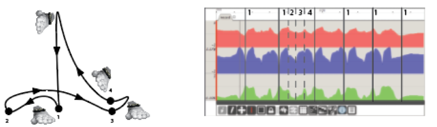
Figure 17. Metronome 120. Counting clear 4/4 patterns
When conducting clear beats in a relatively fast tempo of 120 bpm, the patterns became much more blurred, as illustrated in figure 17. The upbeat to first beat was still evident, especially on the Y-axis. As before, the X-axis showed peak points at first and second beat, though these were much blurrier than before. Also as before, the Z-axis was somewhat obscure and irregular:
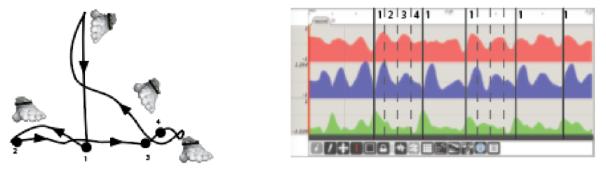
Figure 18. Metronome 120. Counting unclear 4/4 patterns
When conducting in more fluid gestures but still with strict upbeat and downbeat to the first beat, the first beat was clearer, but the whole pattern became blurrier (Figure 18). This happened since the up/down beat to the first beat was accented while the other beats (second, third, and fourth) were less accented or even not at all.
Assessment of sensor ability to capture metric motion
As expected, conducting a straight and clear 4/4 pattern provided acceptable results in the form of repeated patterns with peaks on each beat. When conducting more freely, the patterns started to get blurry. The same happened with increased tempo, with a faster tempo resulting in less predictable patterns. Using the MuBuForMax-hhmm program learn the conducting patterns resulted in precision rates between 50% and 80%, an unsatisfactory result in light of the artistic goal of the ConDiS system.
It is simply a fact that conductors like to use expressive conducting gestures for conducting tempo, meaning they insist on being able to use patterns that go beyond the strict metric gestures. They are musicians too and they need to express themselves freely, as conductor Halldis Rønning clearly states in the interview appended to this dissertation. For this reason, the results when conducting a 4/4 beat revealed that it would be impossible to use the MuBuForMax–hhmm learning feature. Another solution would have to be found that would allow the conductor to conduct tempo as freely and musically as possible.
Circular motion (non-traditional gesture)
Although circular motion is not a part of the conductor’s vocabulary in the way the up/down motion and metric patterns are, it was necessary to ascertain if this type of motion would be useful in realizing the original idea of having the conductor control the panning of the electronic sound. The notion was that if the conductor made a gesture significantly different from any traditional ones, there would be no confusion between the conductor and the performers. Circular motion probably best satisfied this requirement since it is hardly used as a traditional conducting gesture. One potential use for circular motion was to control spectral location of a sound.
The objective was to detect circular motion with the arm held up above the head and moving clockwise around the head:
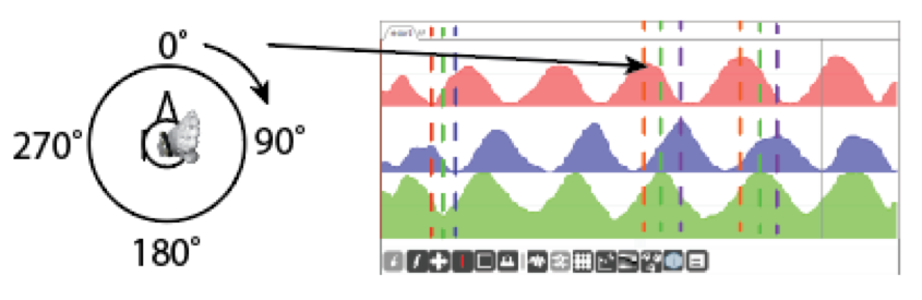
Figure 19. Left arm overhead moving 90° per sec.
Circular motion with the left hand over the head, the palm facing right and moving one circle 360° per 4 sec. or 90° per 1 sec., or the equivalent of a tempo of 60 bpm. As can be seen in figure 19 the pattern is very clear and linear on all the axes. The X-axis shows the high point at 0° and the low point at 180°. The Y-axis has a high point at 180° and a low one at 0°, or a phase of 180° from the X-axis. The Z-axis point is in a +- 90° phase from the other axes with high points at 90° and low points at 270°.
Assessment of sensor ability to capture circular motion
Moving the arm in a circular motion provided a clear and reliable result, certainly good enough to be used in the early development stages of the ConDiS system. It was used, for instance, when Arne Johansen conducted the Jonsvatnet Brass (p. 74). Later I decided not to use it for the final version for aesthetic reasons. Having the conductor moving his arm in circles proved to be a very distracting gesture that seemed to have more to do visually with the rodeo than contemporary music performance. I later determined that holding the arm straight out and twisting it from left to right gave a similar result.
Circular motion with the left hand 90°out from the body moving left-right, right-left.
The ConDiS system and its Graphical Interface

Figure20. The ConDiS Graphical Interface
Figure 20 shows the graphical interface of the ConDiS system (red highlighted squares) as used in conjunction with the Ableton Live digital audio workstation (DAW). The system is originally written in Max/MSP and Max for Live.
- The accelerometer of the x-OSC sensor. The blue column (Y-axis) is used to sense the position of the conductor’s left arm, which is in a high position in this illustration.
- The “ConGlove” finger bending device. Senses finger signs to activate various functions of the system.
- The synchronization and metronome device. Senses the button-clicking function of the “ConGlove.”
- The volume control device. Senses the arm position of the conductor. If the arm position is high, the sliders are high. Conductor can select which instrumental group she activates by straightening out her finger or closing her hand to activate all.
- The metronome of the DAW related to the metronome button function of the ConDiS system.
- The Conducting track. If selected (as it is in the picture), the ConDiS device board is visible.
- The instrument tracks showing instruments either as groups, e.g., woodwind, percussion, and strings, or as individual instruments. Fig. 20 shows the flute.
- The “automated” effect track of the flute. It is showing the automated reverberation of the flute track.
- The “automated” surround track of the flute. Showing how the flute sounds move in space.
- The “markers” written in the DAW that relate to the same markers (numbers) written in the score. This is the backbone of the ConDiS synchronization function, as pressing the jump forward button would move the play head of the DAW to the next marker while jump backward takes it back to the previous marker.
The ConDiS Software
ConDiS is intended to be accessible to others without the presence or involvement of the developer. It is intended to be flexible and open for personal adjustments and/or individual experimental development, an essential component in the artistic philosophy behind the ConDiS project. Therefore the decision was made to use Max/MSP, Max for Live, and Ableton Live, a commercially available software that is user-friendly and yet flexible enough to fulfill the artistic needs of the project. This software is commonly used by composers, performers, software designers, researchers, and artists to create various forms of artistic performances and installations. This is an important factor in choosing appropriate software. The following is a brief description of the ConDiS system, its interface, and the Max/MSP graphical programming as it appears when used in conjunction with the Ableton Live digital audio workstation (DAW). For more detailed instructions on the practical use of the interface, see Chapter 6, Performance Preparation.

Figure 21 shows the graphical interface of the ConDiS system. The following uses the first device, the “xiovalue,” as an illustration of the Max software programming that lies behind the system.
A closer look at the ConDiS system
Figures 22 and 23 provide a more detailed view of the receiving messages of the “xiovalue” or the x-OSC device as it is implemented in Max for Live.
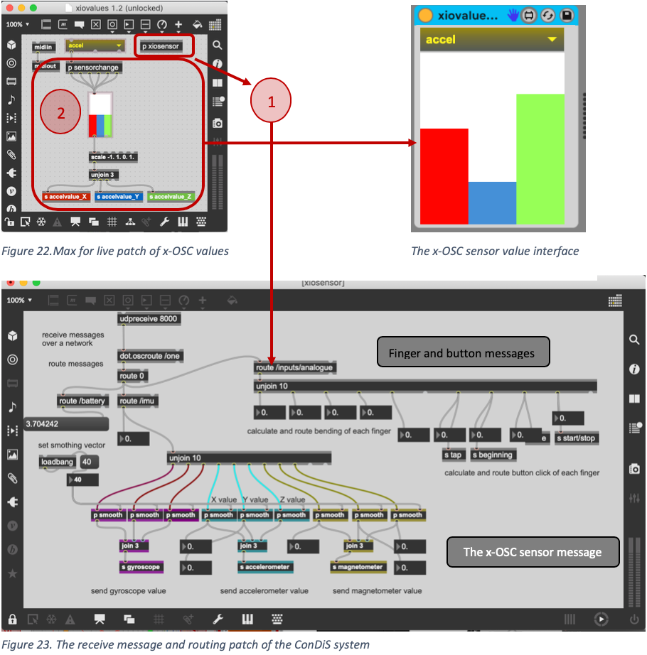
- The patch “p xiosensor” receives messages over a network and routes to various functions of the system. Messages are sent from the on-board sensors (gyroscope, accelerometer, magnetometer) alongside an analogue signal from the bending sensors on each finger as well as the glove’s four buttons.
- The patch “p sensorchange” selects the sensor (gyroscope, accelerometer, magnetometer) to be activated.
DAW and Digital Sound Processing (DSP)
The signal chain of the DSP is one of the crucial parts of the electronic sound. It is “the thing” that happens in the middle, thus the DSP chaining setup determines the sonic outcomeof the electronics. Figures 25-26 shows the DSP in conjunction with the DAW. At this point it will be helpful to take a closer look at the mixed music model that was introduced above on page 4.

Figure 24. The mixed music model of Kuuki no Sukima showing the process as three forms of activity: Human, Digital, and Object-oriented. Here the conductor’s volume control is added to the process.
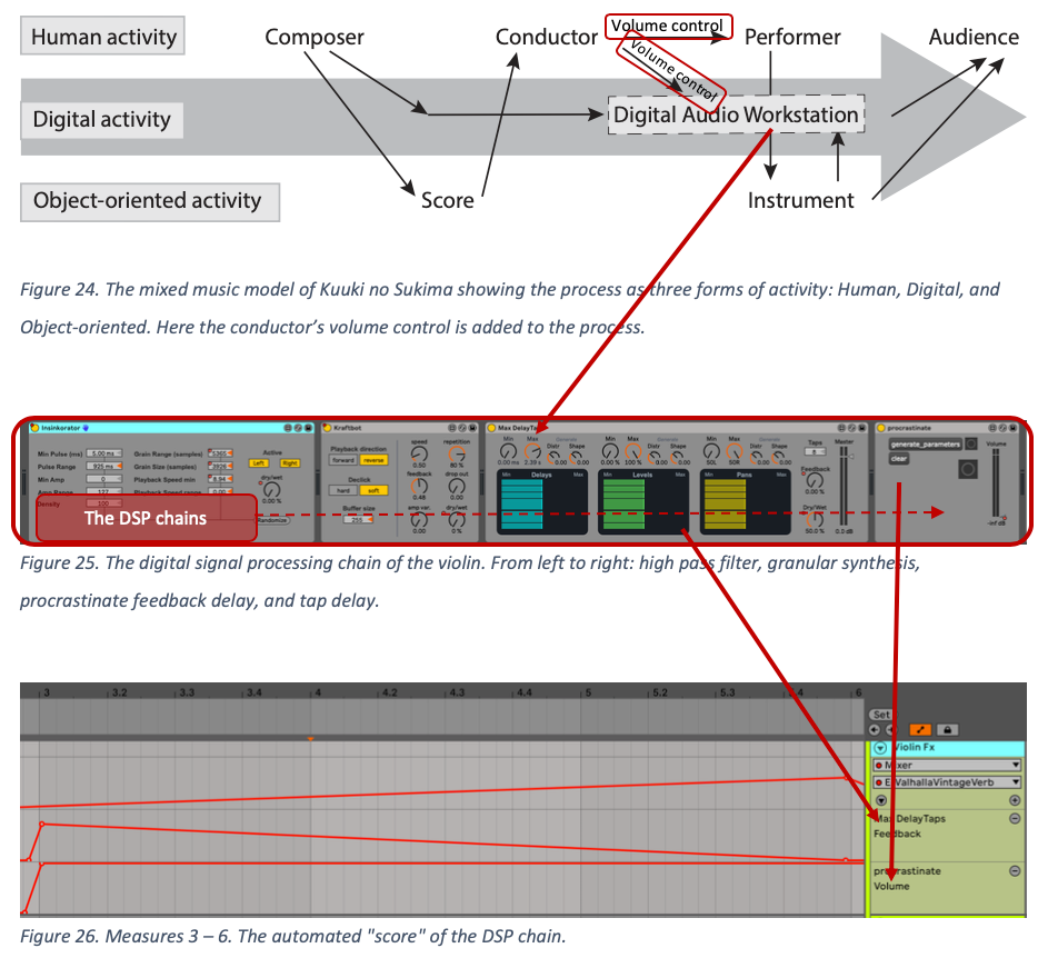
Figure 25. The digital signal processing chain of the violin. From left to right: high pass filter, granular synthesis, procrastinate feedback delay, and tap delay.
Figure 26. Measures 3 – 6. The automated “score” of the DSP chain.
As shown above, the DAW sound processing in Kuuki no Sukimais entirely automated, meaning the conductor has no control over the electronic signal other than adjusting sound volume output.
Conducting Gestures and Signs
Controllers and signs.
Controlling electronics using Conducting Gestures
Testing various conducting gestures to activate, control, and conduct the electronics, has been a crucial part of the research. Seeking for answers to questions like how to add these controls to the conductor’s gestural library? Is it possible to use classical conducting gestures only, or do I need to invent new gestures?
The professional orchestral conductor has trained for years her musical gestures, and it may be difficult to ask her to learn new, let alone many new ones. Why not use the same gestures since the conductor is conducting very similar elements in the electronic as for the acoustic instruments? Therefore, making the use of ConDiS less noticeable or invisible. The following is a short introduction to the gestural solutions used for controlling various parameters of the digital workstation.
Gestural Functions
The controllers (parameters) that originally were thought to be controlled by the conductor were grouped into the following categorization:
- Overall volume (amplitude).
- Spatial location (pan).
- Sonority and spectral timbre (effect).
- Conducting tempo (tap tempo)
- Synchronization between conducting score and electronic score.
To signal the computer witch parameters should be controlled a use of sign language turned out to be the simplest solution. Using sign language is nothing new for conductors, as this solution proved to be very good.
For the conductor to activate the controlling features the following action had to be taken:
Close fistto signal the computer DAW that control action is about to be executed.
- Make an OK sign to activate volume control, then move arm up or down to adjust volume level.
- Make a thumb up sign to activate spatial location (pan), then twist arm to move the sound in space.
- Make a little finger sign to activate effect control, then move arm up or down to adjust the effect volume.
Open handto deactivate all control features and therefore being able to conduct freely without affecting the electronic sound.
- To control tempo (tap tempo) the conductor has to press a button on second finger four times in the suggested tempo.
- To synchronize the written score and the electronics of the digital workstation the conductor has to press the following buttons:
Third finger button to stop and start the DAW
Fourth finger button to jump forward to the next marker of the DAW
Fifth finger button to jump backward to the previous marker of the DAW
Multi click the fifth finger button to jump to the beginning of the piece.

Figure 27. Sign language to signal various control features to the computer DAW
As mentioned earlier the panning and the effect control functions were left out for the final version of the ConDiS system. Keep in mind that the fundamental idea of ConDiS was to extend the traditional job of a conductor allowing her to conduct and control the electronic sounds as she does with the instrumental sounds. Therefore, in its basics, the conductor’s job is not to conduct and control the spatial location of the sound nor to control the sonic timbre. These instructions are all written in the score beforehand. Still, these functions were realized, and it turned out to be a too complicated task. To have the conductor doing his traditional job of interpreting the written score, controlling the volume and tempo, cueing and synchronizing while simultaneously moving and panning the electronic sound turned out to be too extensive for our multitasking abilities.
All these factors have been realized and do function as shown in the following video examples.
Volume control (Overall volume).
Figure 28. Video example. Volume control (video demo)
The conductor can raise or lower the overall volume of the electronic sound. With simple finger gesture, an OK sign, the conductor can trigger the volume control feature “on” and then by lifting left arm raise the sound. When the volume level is at “right” level, the volume control is triggered “off” by closing the hand. Same goes for lowering the sound except the arm must be lowered. (See Figure 28).
The use of a traditional up/down arm gesture to indicate increase or decrease of sound levels gave a positive artistic result. It was well suited to the traditional conducting gestures for
Pan control (spatial location)
Figure 29. Video example. Pan Control (video demo)
The conductor can move sound in space. He can with finger gesture (thumb up) trigger the pan control feature and then by tilting the hand move the location of the sound. As with volume control, the pan control function is deactivated (turned off) by closing the hand. (See Figure 29).
Effect control. (sonority and spectral timbre)
Figure 30. Video example. Effect control (video demo)
The conductor can raise or lower the overall effect volume. He can with finger gesture (little finger out) trigger the effect control feature and then by lifting or lowering left arm raise or lower the sound. The effect control function is turned off by closing the hand. (See Figure 30).
Conducting tempo (tap tempo)
Figure 31. Video example. Tempo control (video demo).
The conductor changes tempo by clicking a button on the middle finger accordingly to a written tempo. The tempo controller can be set to calculate the average time between any number of clicks. That means it can calculate the time between two clicks minimum to an infinite number. If the score is in 4/4 a calculation setting of 4 would be the most natural setting although a setting of 2 can efficiently work. For pieces with frequent meter changes a setting of 2 seems to give the best result. (See Figure 31)
Cue control. (Synchronization of conducting score and electronic score)
Figure 32. Video example. Cue control (video demo)
The conductor can, by clicking buttons on the ring finger and little finger move the electronic score back and forth to selected numbers (rehearsal numbers) written in the score.
Expressions and “natural” emotions
As can be seen clearly in the above videos, the emphasis was on making use of the conducting glove as normal to the conductor´s gestures as possible. With this, the conductor could focus on his traditional way of conducting with the same natural emotion and expression to which she is accustomed. It can easily be argued that pushing buttons is not a conducting tradition or a very expressive way of conducting. These arguments can surely be accepted, but this was the simplest solution in the situation where gesture recognition technology was not reliable enough. During the development period, attempts were made to use “force sensitive resistors” to give the conductor a better feel using her fingertips. Unfortunately, that experiment did not give as good result as the buttons due to instability and complications related to accidental touches such as when opening and closing hand. One of the future goals of the ConDiS system is finding a genuine solution to get rid of all buttons since they are not in parallel of the philosophy of the ConDiS system. A philosophy of making a conducting tool that is a “natural” extension of the conductor´s conducting tradition.
Making the conducting tool.
Designing the hardware
One of the first ideas of the ConDiS hardware or tool was to extend the use of the conductor’s baton by making a digital pole/baton. A prototype of a baton was made, and various gestures recorded to find what kind of patterns it would make.
To measure the conducting gestures, the MuBu multi-buffer program from IRCAM running Max/MSP on OSX was used. (Ircam, n.d.)The type used for the ConDiS motion analysis was; mubu.hhmm (Hierarchical Hidden Markov Models) based on the hhmm_leapmotion_recognition program by Masayuki Akamatsu (Akamatsu, n.d.)and slightly modified for the use of x-OSC Wi-Fi board.
The ConBat (Conducting Baton)
The first idea was, not to surprise, to think historically. What of making a baton that could be used similarly to Lully´s conducting baton?[1]A romantic and interesting idea, but much too limiting and unnatural for the conductor. The second idea was more practical and more in the spirit of Curtis Road´s idea quoted earlier of the conductor’s baton to be the original remote. A prototype was made of a conducting baton that contained a sensor in the shaft. Admittedly, it would be great if just a technological upgrade of the traditional baton would be the answer. After testing the baton, reading out various gestural patterns, I concluded that to use a baton was too limiting for the conductor and for confusing for the performers. Through the baton, I realized that using design of a conducting tool that was based on the classical conductor’s baton was probably not a good idea. The main reason being that the conductor holds the baton in her right hand which is the hand that is used to give the basic tempo and volume indications to the orchestra. Tempo given with clear metric signs and volume with smaller or bigger gestures. To have this also linked to the electronics made it difficult for the conductor to divide her conducting between the performers and the electronics. It also made it difficult for the performers to distinguish when the conductor was conducting the orchestra or the electronics. Another important part of orchestral conducting is the conductor contact to individual performing groups. If she needs to get the message to the Brass section to play softer than he does so by looking at them, usually gets eye contact, and signals less volume. That signal is usually given raising the left arm and then lowering it. Action that would be impossible to do with the sensor in the right hand. There it was judged as the best alternative to put the ConDiS conducting tool to the conductor’s “fingertips” or even better in the hands of the conductor, hence the conducting glove the “ConGlove.”
The ConDiS Conducting Glove (ConGlove)
The decision to make the conducting tool in the hands of the conductor was somewhat disappointing but logical. It was disappointing because I had hopes of inventing something totally new and original. Thus, making a digital glove was far from that dream. There are so many gloves out there. Although most of them used in virtual reality environments and video there are also to directly control audio like the Imogen Heap’s “mi.mu” Glove.(mi.mu, n.d.)mentioned earlier ( p.44) The main difference though, being the aim of the ConDiS project to create conducting tool for music conductor that is based on and adds on to the tradition of classical conducting.
The conducting glove is designed to enable a conductor not only to control the overall mix of the performing musicians and the electronics but also to synchronize the performers and associated DAW. In other words, conducting the overall balance/volume, tempo and synchronize written score and DAW. ConDiS is directed toward new possibilities in musical composition and the interaction, the expressions, the musical gestures and movements of the classical conductor.
The following section is written to give a better understanding of the functions of the conducting glove (hereafter, referred to as the ConGlove). This writing is by no means a complete explanation but as an introduction providing an overview of the ConGlove’s usability with regard to “Kuuki no Sukima.”
The ConGlove
Steinar Brandslet writes in an article published in Gemini, Research News from NTNU and SINTEF:
The composer Hilmar Thordarson found this glove on the street, and decided it deserved a new life — as a tool for conductors. The glove now has wires, buttons and sensors that can sense different movements and send the information to a computer. (Brandslet, 2019)
ConDiS – Conducting Digital System consists of a glove controlled by x-OSC wireless I/O board that communicates over Wi-Fi using open sound control[2](OSC). Software based on Max / MSP sends information from glove through Max4Live to Ableton Live digital audio workstation. The conducting glove is designed to enable a conductor not only to control the overall mix of the performing musicians and electronics but also to synchronize the performers and associated DAW.
In other words, conducting the overall balance/volume, tempo and synchronize written score and DAW at selected cue-points written in the score. ConDiS is directed toward new possibilities in musical composition and the interaction, the expressions, the musical gestures and movements of the classical conductor.
Figure 35. There are four buttons on the inside of the ConGlove, each with a designated function.
Functions of the ConGlove
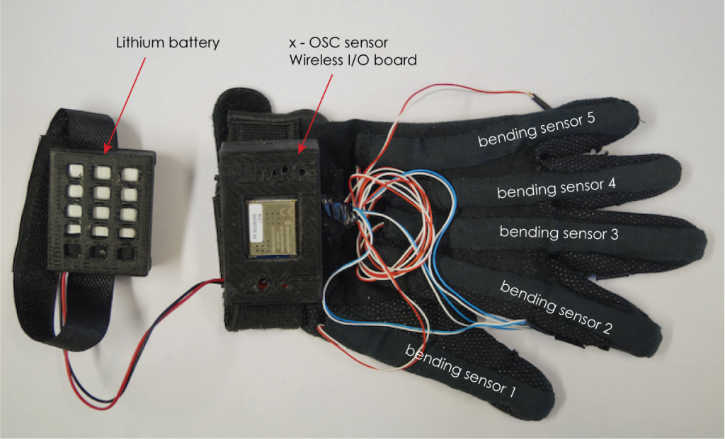
Bending sensors
There are five bending sensors “built in” the conducting glove. One for each finger allowing use of sign language to send messages to the DAW. For instance, by sending out message holding out the thump the DAW reads the message as value of one (1), holding out index finger as value of two (2) holding out middle finger as value of four (4), ring finger as value of 8 and little finger as value of 16. Any combination of fingers would then be the sum of the fingers for example holding out thumb and index finger would give a value of 1+2 = 3 or combination of index and middle finger (a peace sign) would give a value of 2+4 = 6. The bending sensors are then scaled to give a value from 0 – 127. 0 indicating fully bend finger and 127 for fully stretch out finger.
OSC x-IO Wireless Sensor
The conducting glove comes with x-OSC wireless I/O board that communicates over Wi-Fi using OSC. It provides up to 32 analog/digital channels and equipment with three onboard sensors; gyroscope, accelerometer, and magnetometer. For the ConDiS system, I decided to use the accelerometer to measure the movement of the conductor’s arm from 0 as the lowest possible position and 127 the max.
Buttons
There are four buttons on the conducting glove, one for each finger except the thumb. It being excluded since the thumb needs to trigger the other buttons. Each button triggers an on/off message with 0 as the “on” value and 1 for “off” value. These buttons are used to synchronize and indicate tempo and cue-points between the DAW and written score.
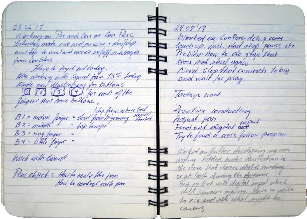
Notebook February 2017.
[1]Jean-Baptiste Lully (1632-1687) was a French composer that used a long conducting staff during a performance.
[2]Open Sound Control (OSC) is a communication protocol for networking computers, sound, and other multimedia devices.